3D Printing a Stylophone
9/13/2025
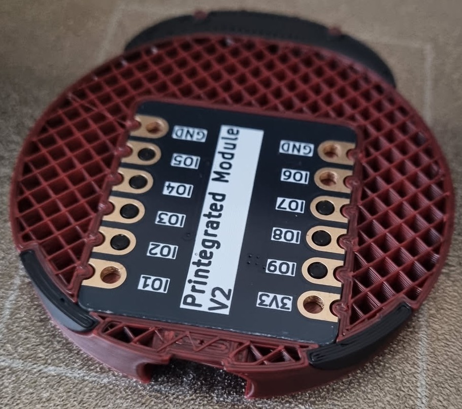
I recently took part in a study on the feasibility of 3D printing circuits using electrically conductive filament. We were given a PCB which basically was just a breakout for a Seeeduino ESP32-S3 that broke out the IO, Ground, and 3v3 lines to much larger pitch holes (2.5mm). This meant that we could insert a pause part way through the print, slot the board onto columns designed to fit the holes, and print over them - sealing the connection.
We had to print a ladybird that acts as a media controller as part of the introduction.
We had to pick something to design and print ourselves, and I had an idea. I’ve wanted a Stylophone for a while, but never got round to buying one not the least because I’m actually not very musical and knew it would just sit there and not get used. So I figured this was a perfect opportunity.
If you don’t know what a Stylophone is, it’s a miniature analog synthesiser played with a stylus.
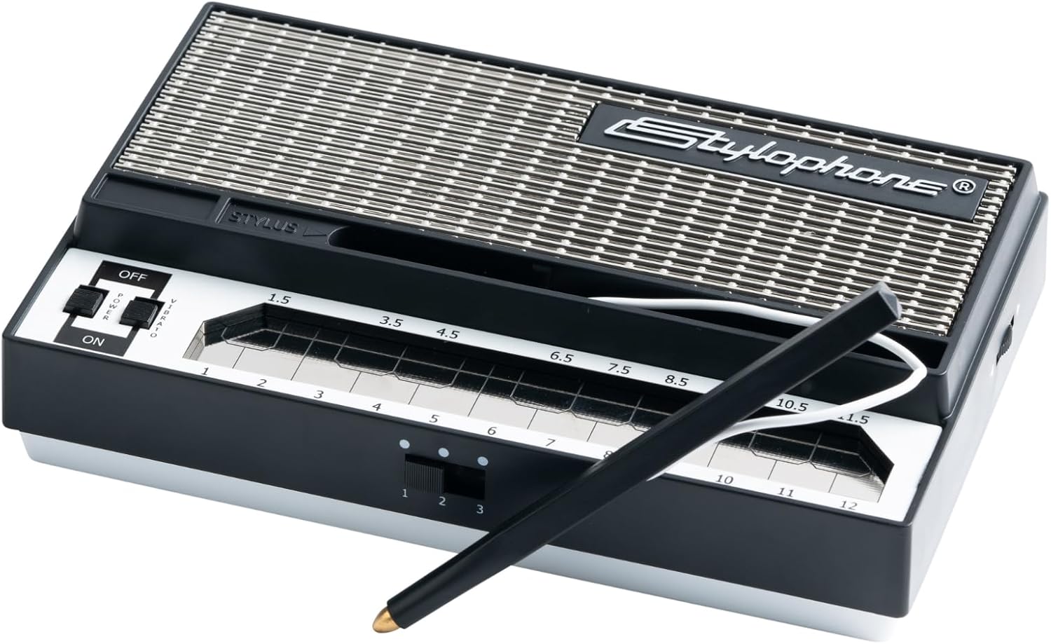
How very Retro.
Design
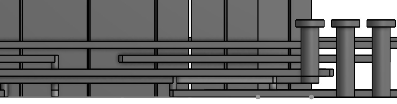
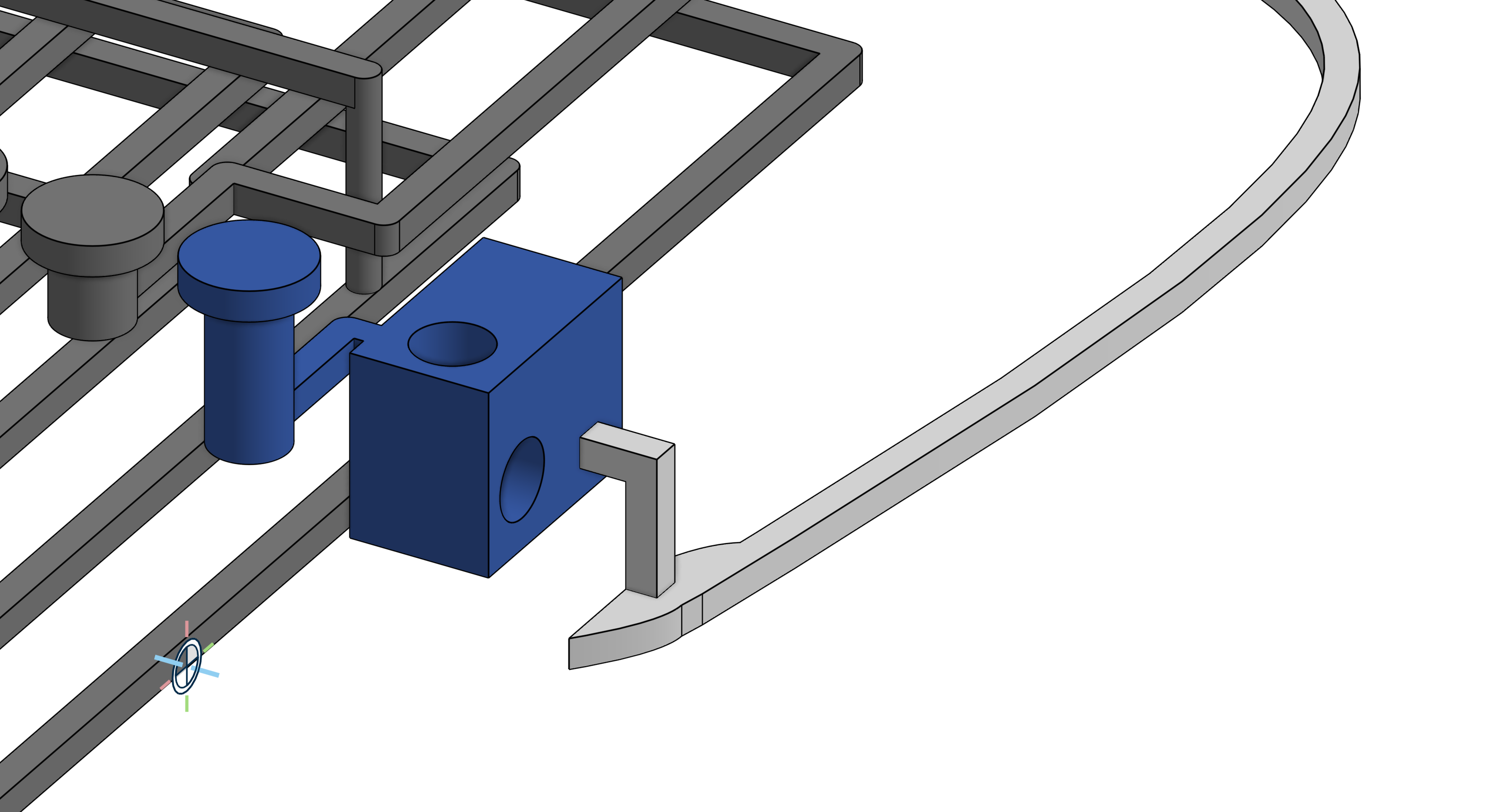
Now my idea was relatively simple, I could print the keys out of conductive filament, run them to IO inputs on the board, and run 3v3 through a stylus also printed with conductive filament. I could continuously read the inputs as analog values, and when a key was pressed I’d see the reading go high.
The catch, of course being that the ESP32-S3 only has nine inputs, and there are 20 keys on the Stylophone.
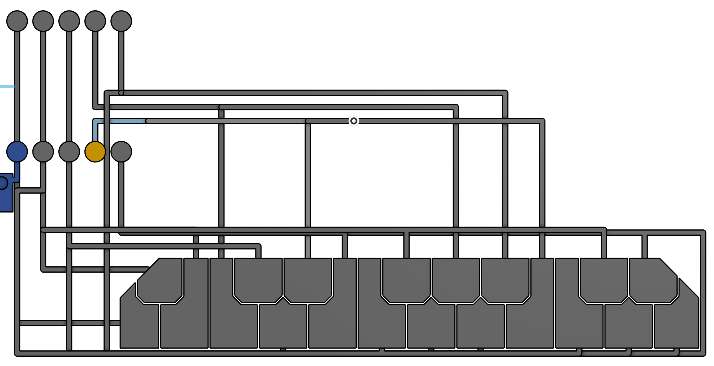
My theory was that I could attach 2-3 keys to each input, and so long as the length of the trace connecting each key to the input was varied enough, I’d be able to tell the difference as they should have different resistances and therefore different readings on the analog input.
For this project, I had to learn Onshape, as my only previous CAD experience was with Sketchup, which is not advanced enough. Honestly, it was really challenging, but very fun and rewarding. It’s a totally different experience to Sketchup, and not something that came naturally to me. There were many things that felt like they were 10x more complicated than they needed to be. Especially making the traces took forever, as some of them changed elevation multiple times which required many sketches.
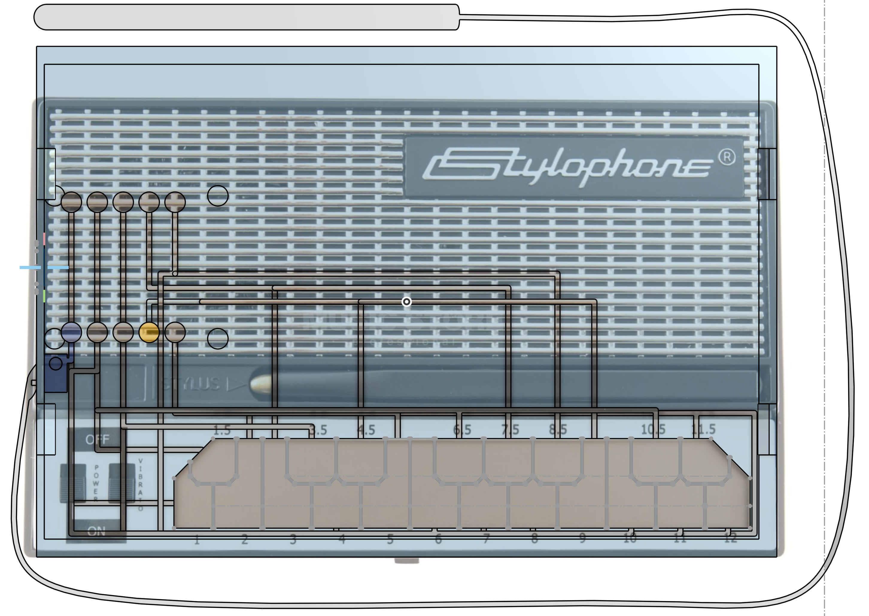
I traced the keys from a photo I found online.
I kind of just eyeballed the traces, and honestly this was the most time-consuming part of the project. I do wonder if there is a faster way to do it...
Sooo tedious.
I 3D printed the stylus too, and had it connect straight up to the 3v3 output. Since I made the connection to the stylus relatively thin, it is flexible enough to work fine. The filament isn’t designed to be flexible, so I figure eventually it’ll break from fatigue, so I added a hole for a wire to go into the side, with space for a screw to hold it up against the conductive filament.
Planning for the future.
Printing & Assembly
Printing took about ten hours for the bottom, and IIRC a few hours for the lid. The vast majority of this time was spent purging filaments, especially since the carbon in the conductive filament is particularly pervasive and requires a large purge volume. The downsides of a single toolhead. Even with the maximum purge volume size, you can see how bad the bleed is in the corner, and in fact the walls are supposed to be bright red too, and turn out a very dark red instead.
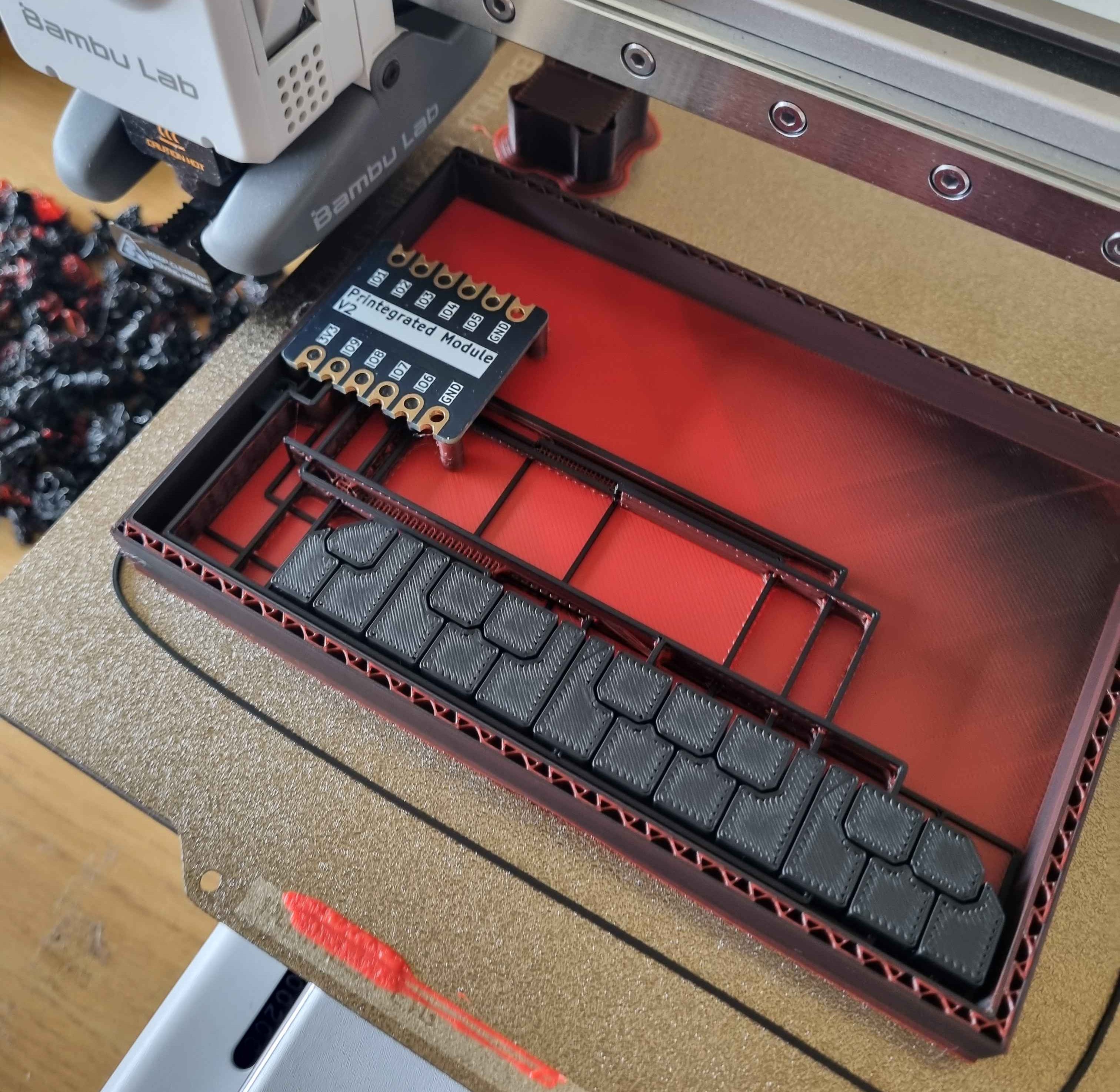
Fit onto the pins perfectly.
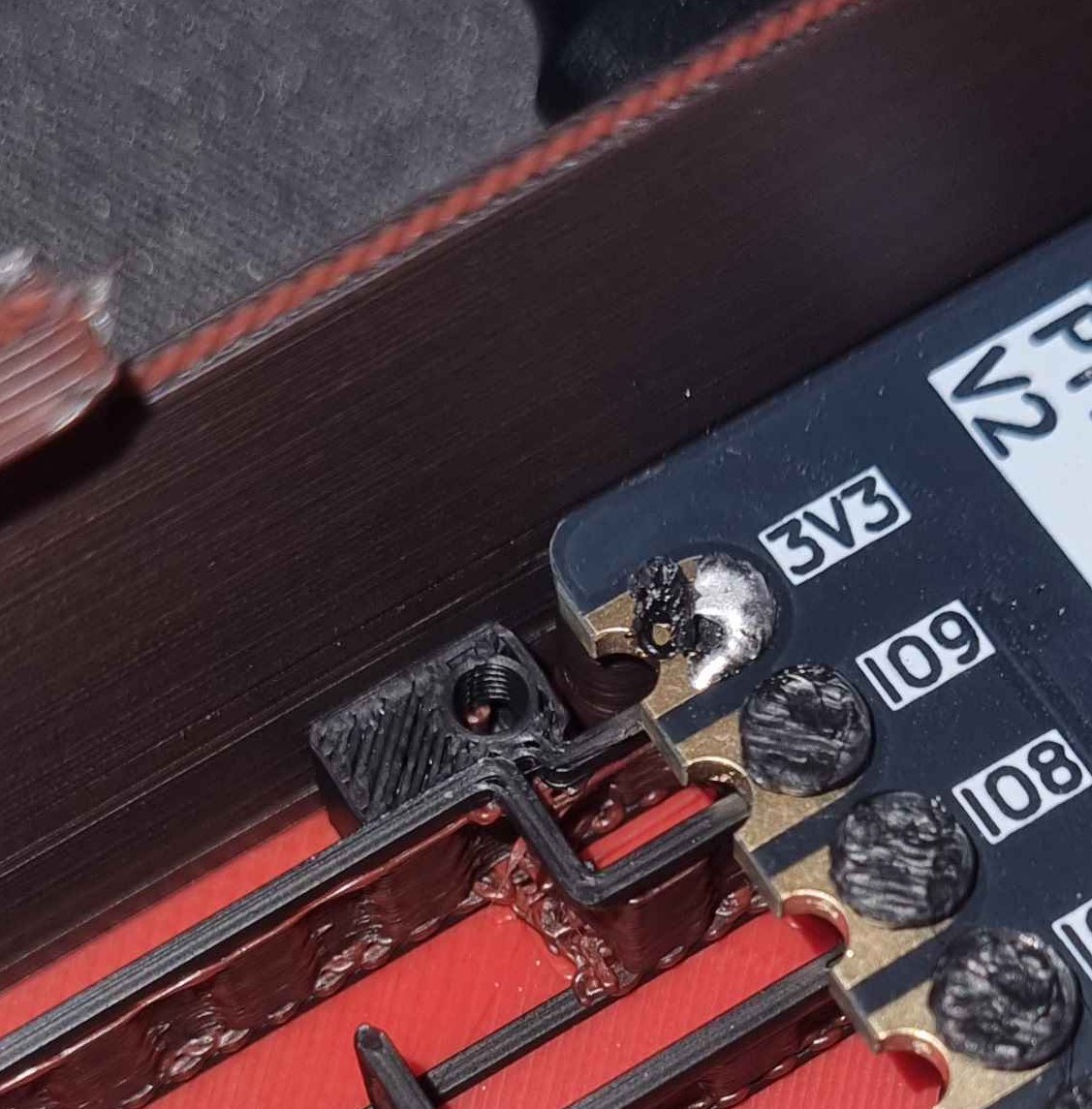
I had to cheat and solder a connection where the cap got knocked off.
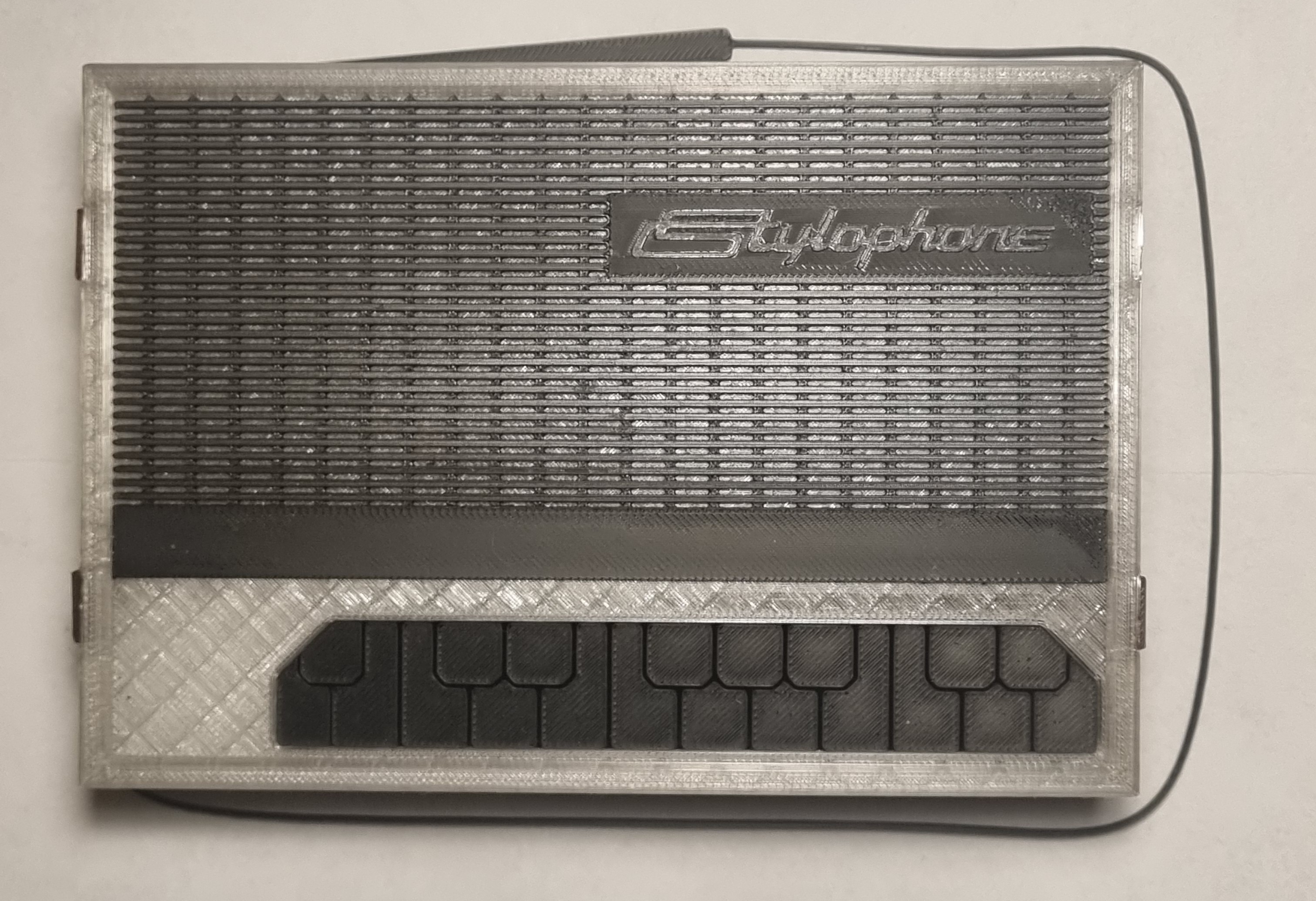
Black for the grille, transparent for the lid body, and glow-in-the-dark for the logo.
Software
I wrote the software in a bit of a rush, so it doesn’t work very well, and requires annoying calibration.
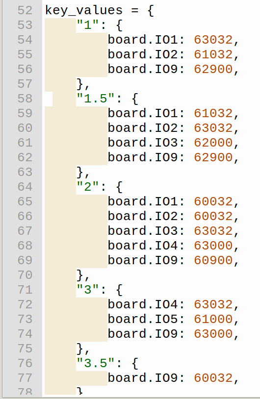
Potential employers: I promise I could implement many solutions better than this.
Conclusion
It works. Sort of.
Problems
The amount of time/filament needed to purge between filament changes is crazy. This meant that the “non-conductive” parts were slightly conductive. Combined with the fact that I put all the traces quite close to each other, there was quite a bit of cross-talk between different traces.
I did not set the internal pull resistors on the ESP to pull the inputs low, so they were floating inputs which made it harder to gauge the resistance.
V2?
I probably won’t pursue a V2, since I’m not particularly musically inclined, but this was a fun project and I wouldn’t mind working on it again. I would change would space the traces out much further apart inside the case, maybe try and find some way to print the conductive parts separately to the shell to improve print times, and also redesign the lid so it can be removed after being put on.